The following is gratefully reprinted with permission of Noel Holley and MilWest Dispatch as published in the May and Aug/95 Issues of MilWest.
CATENARY FOR STEAM RAILROAD ELECTRIFICATION
By Noel T. Holley
Editor's Note: The following is a reprint of a clinic prepared and presented by Noel at the MilWest Annual Meet in Cle Elum in 1993, as well as other times and locations. It is reprinted here for the benefit of those who have been unable to attend this clinic in person. The information presented should be of value to anyone attempting to model Milwaukee electric operations. Noel is the author of "The Milwaukee Electrics", published in 1987 (and reprinted in 2000) He did extensive research in preparation for the book including direct consultations with Laurence Wylie, the Seattle based electrical engineering consultant for the railroad. This book is arguably the best book ever written (at least in the latter part of this century) on the Milwaukee electrification. Rocky Gibbs
THE PROTOTYPE
There were three primary reasons for the adoption of catenary type overhead wires on railroad electrifications. It provides a level contact wire, it can easily deliver more current than a single wire and it requires fewer support poles than does a single wire.
A level contact wire is valuable in high speed operation in order to keep trolley poles or pantographs from bouncing off the wire. If pantographs are in use, a level may even be critical. While trolley poles have a whip-like flexibility which allows them to follow undulations and maintain contact with an uneven wire, pantographs are comparatively slow to respond to changes in wire height. Pantographs are essentially a stiff set of levers and springs. At speeds above 60 MPH, they can be observed to bounce off of a trolley wire which sags between the support poles. This bouncing can result in arc flashes, arc burns on the pantograph shoes, and momentary power loss for the locomotive.
The need to deliver high amounts of current arose when railroads began operating heavy trains electrically. Five car Sacramento Northern interurban passenger trains typically drew 450 amps continuously at 1,200 volts. These trains were heavy for an interurban line. A Milwaukee Road Little Joe exerting its frill starting tractive effort drew 3,400 amps at 3,000 volts. It drew 2,720 amps continuously when producing 5,110 horsepower. With current loads like these, a single wire overhead would burn down from being overloaded.
The Sacramento Northern installed catenary to deliver the amps. High speed passenger trains were equipped with trolley poles, but the amperage load was at the limit of that which a trolley wheel could collect. Excessive current loads will burn up trolley wheels and their wheel bearings. SN freight locomotives used pantographs. The broad, flat, pantograph shoes allowed the freight motors to collect lots of amps without arcing and burning.
On steam railroads, the use of trolley poles was out of the question. The amount of current drawn by mainline locomotives was far beyond the limits of trolley wheels and trolley slider shoes. In addition, speeds were sometimes high. Pantographs were needed to collect the current. Catenary was needed to carry the current and to hold the contact wire level.
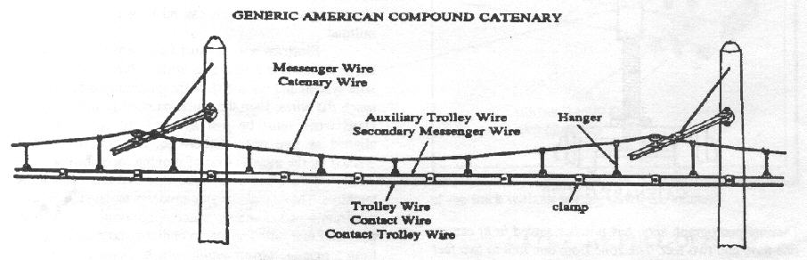
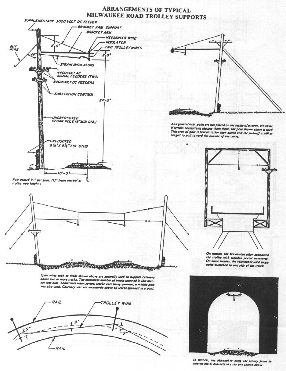
To meet the power needs of large locomotives in heavy service, the steam railroads developed some variants on catenary which were unneeded on interurban lines. The Milwaukee used a type of simple catenary called Double Trolley This consisted of two copper trolley wires suspended side by side from a steel messenger wire. The Great Northern used simple catenary consisting of a single bronze trolley wire suspended from an extra large copper wrapped bronze messenger wire. On roads such as the Pennsylvania, Virginian, and Norfolk & Western, a design was used which is called Compound Trolley, Compound Catenary or Duplex Catenary. Different terms were used by different electrical engineering firms. A bronze trolley wire is supported by a copper auxiliary wire, which is supported by a bronze messenger wire. Ml of these variations on catenary design substantially increased the amount of current which could be carried by the catenary.
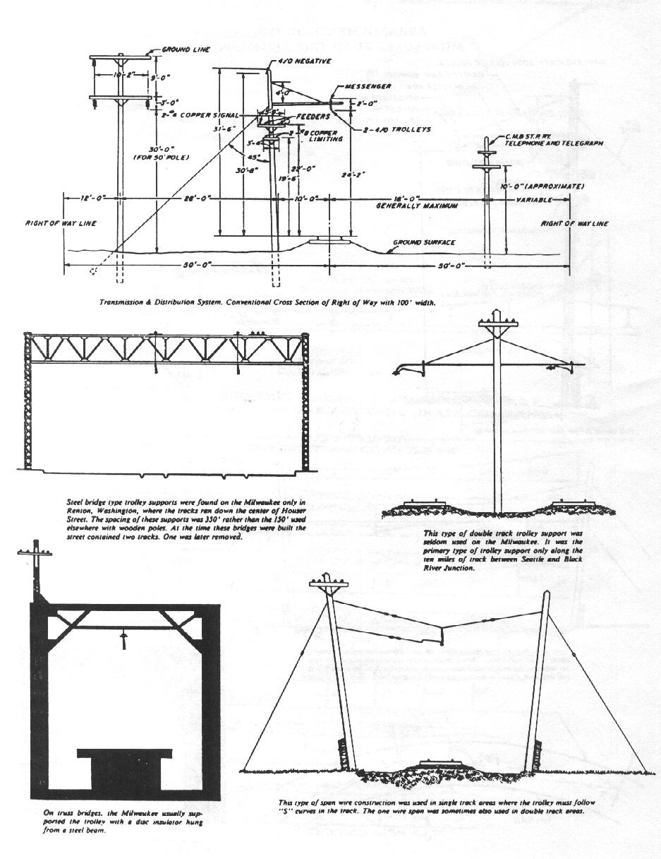
The third reason for building catenary was to keep down the number of support poles needed for the overhead. Single wire overhead typically requires a support pole every 80 to 100 feet Greater spacing would allow an amount of sag which is excessive even for the use of trolley poles. If the single wire is large enough to carry the amount of current required for heavy locomotives, an even closer spacing may be necessary. By using catenary, a railroad could increase the spacing to as much as 150 to 200 feet and still use wooden support poles. If steel poles were used, 300 feet became practical. Wide pole spacing brought about significant cost reductions in long distance electrifications.
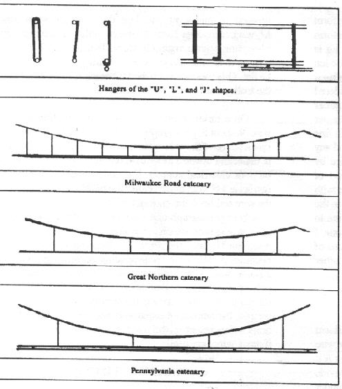
The characteristic appearance of catenary is a gracefully sagging messenger wire supporting a perfectly level contact wire The two are connected by hangers of varying lengths. The color of typical American catenary was the bluish-green of copper oxide and bronze oxide in many locales. This was particularly true in humid climates with salt air. On the Milwaukee Road the color was a dark rusty brown in most places. The messenger wire and hangers were made of galvanized steel and when that plating wore off they rusted. The contact wire was copper, but in dry climates copper turns brown rather than green. On rail lines where large numbers of steam engines ran under the wires the catenary was blackened with soot.
MODEL BUILDING
Only a few American modelers have ever built catenary. That is probably because the difficulty level is roughly equal to building hand laid track. Some of the catenary which has been built has a somewhat unprototypical appearance. The messenger wire does not sag, the contact wire height is too low and the support poles are very close together. Some compromises are necessary when building a model but others can be avoided by using improved construction methods and referring to prototype standards.
CATENARY MATERIALS
My catenary is built of .015 piano wire. It is a spring steel wire which is available at most hobby shops, especially those which sell model airplane supplies. It costs 10 to 20 cents each for three foot sections. I recommend this type of wire because it is sold in straight sections, it is very strong, and if it is bent into a shape, it will hold that shape. In addition, it is inexpensive. Thin brass wire is used for the hangers which link the trolley wire to the messenger wire. Steel does not solder easily with the commonly used lead-tin solders. It order to solder it effectively, one of the types marketed as low temperature silver solder must be used. STAY-BRITE brand is very good and many hardware stores carry that or equivalent products.
Types of wire used by others in building catenary include phosphor-bronze, spring brass, and nickel-silver. These types of wire have a much higher electrical conductivity than steel and nickel-silver is resistant to oxidization. These wires also have the advantage of being easy to solder, but it is difficult to straighten them. They are sold on spools or in coils and they tend to coil or snake unless put under tension. The tendency to coil makes it difficult to use these wires on a jig. The need to apply tension to combat snaking makes it difficult to build a prototypical sag in the messenger wire. Copper wire is not useful in building model catenary because it is too soft and it tends to stretch if put under tension.
MESSENGER TO TROLLEY DISTANCE
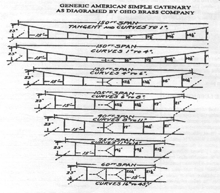
On the Milwaukee and the Great Northern, the messenger wire and the trolley wire should be three scale feet apart at the peaks. On catenary for the Pennsylvania and the Virginian they should be six feet apart at the peaks. Minimum distance depends on the pole spacing. Refer to the Simple Catenary Diagram for minimum hanger lengths The Pennsy and Virginian catenary uses an auxiliary wire which is about two inches above the trolley wire.
CATENARY CONSTRUCTION
The wires must be laid out on a jig, or on the trackside catenary supports. Then it must be put under enough tension to make it lie straight. Next, use needle nosed pliers to bend peaks into the messenger wire. These peaks must match the spacing of the poles. After lining up the wires the way you want them to look, solder the hangers into place. Since the catenary will require a large number of hangers, an easy to work with type should be used. One end should be easy to hold in place while soldering. The other can be trimmed to fit, after the solder cools.
The Milwaukee and the Great Northern used loop hangers. These can be constructed using inverted 'U' shaped pieces of thin brass wire. An "L" shape will also work, if loops appear too troublesome to make. Lines such as the Pennsylvania, the Virginia the Norfolk & Western, and the South Shore used straight wire or rod hangers. These can be modeled by using "J" shaped pieces of wire which hook under the auxiliary wire.
Milwaukee catenary hangers will look correct if the hangers are spaced ten scale feet apart. Great Northern hangers should be fifteen feet apart On the Pennsylvania, hangers from the messenger wire to the auxiliary wire should be thirty feet apart. Between each pair of hangers are clips connecting the auxiliary wire to the trolley wire. To simulate these clips, use copper wire which is the same diameter as the brass hangers. After the hangers are soldered in place, stick copper wires in between the trolley wire and the auxiliary wire. Make sure they are properly located, then solder them in place and clip the ends.
SPLICING SECTIONS OF CATENARY
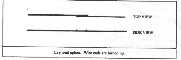
When soldering sections of catenary together, lap joints should be used. An overlap of 1/4 inches in the wire makes a very strong joint which will not pull apart under tension. The trolley wire ends should be turned up slightly at each end to assure that they will not snag passing pantographs. Because this catenary is designed for pantographs rather than trolley poles, there is no need to make butt joints in the wire.
FILE THE TROLLEY WIRE SMOOTH
After hanging the catenary, file all trolley wire solder joints smooth. The solder at splice joints, hanger connections and pull-offs may be lumpy or rough enough to cause problems for pantographs. Excess wire may even form hooks which could snag a pantograph. After filing them, inspect them with a hand held mirror or an old dentist's mirror. A trolley wire which is rough or bumpy will cause poor electrical contact. In addition, bumps and snags can severely bend a pantograph or tear it loose from the locomotive.
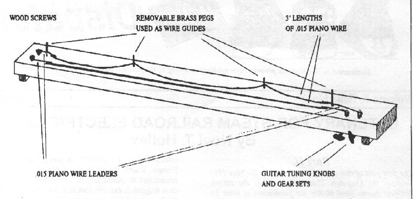
CATENARY CONSTRUCTION JIG
It is difficult to make catenary which has a uniform amount of sag in each span. In order to make uniform appearance practical, I construct mine on a jig. The jig is made from a hardwood board 48" x 4 1/2" x 1/2". Wooden blocks are glued under it for legs. Guitar tuning gears are used to position the wires on the jig so that they can be soldered into catenary The tuning gears were given to me by a guitar repairman. They came from his junk bin and can no longer hold an instrument in reliably in tune, but they work just fine for my jig. The jig can be adjusted for any span length and any distance between the messenger wire and contact wire by simply moving the brass guide pegs around. Any sort of catenary, from a type with a great deal of sag, to a type with very little sag can be modeled by adjusting the tension on the messenger wire, with the tuning gear. The jig allows me to rapidly make sections of catenary which are three feet long. I have used it to make a catenary out of three foot sections of .015 piano wire. It may be possible to use the jig with other materials, but I have never tried it.
CATENARY TENSIONING
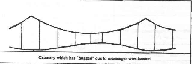
On a prototype railroad, gravity exerts a significant downward pull on the catenary Even though the trolley wire is under 2,000 to 8,000 pounds of tension, it would sag if it were not supported by the messenger wire. In order to provide support, the messenger wire is designed to sag and is under roughly equal tension, If, however, the messenger wire is excessively tensioned, it will pull the trolley wire upward at midspan. The trolley wire will then no longer be horizontal, it will be distorted into a wavy pattern which rises and falls like a hog's back. Hogged catenary could be seen on prototype railroads when cold weather caused the messenger wire to contract. I observed this on the Milwaukee, and a consultant study noted it on the Pennsylvania. When this occurred, wire maintenance crews had to adjust the wire tension in order to make the trolley wire level again.
Gravity does not operate to scale. As a result, there is no significant downward pull on model catenary There is nothing to counteract tension in the messenger wire, thus any tension is excessive tension. It has been my experience that a messenger wire with any tension on it will pull the trolley wire upward in mid-span and hog the catenary some extent. Milwaukee modeler Keith Newsom builds his catenary out of phosphor bronze wire. He found that he could have some tension in his messenger wire and still get the trolley wire to lie flat. This was accomplished by cranking up the tension on the trolley wire.
On a model railroad, tension is required on the trolley wire. Without it, will cause the catenary to deflect upwards and to the side in midspan. If the catenary is capable of deflecting upward more than one scale foot, the result may be poor electrical contact. If it deflects sideways more than two scale feet from track center, the pantograph may come off the wire and hook the catenary with its horns. This will result in a bent pantograph and possibly torn down catenary The amount of tension which is required in the trolley wire can be determined by trial and error. The required amount of tension becomes greater as the pole spacing becomes greater. Up to a point, steel wires will stay tight, if they are strung tight. If pole spacings greater than about 120 scale feet are used, the catenary will need spring tensioning. According to some people, the amount of expansion and contraction in bronze, brass and nickel-silver will make spring tensioning a necessity if those wires are used.
CATENARY OVER CURVES
Prototype catenary is built to follow curving track in one of two ways. A series of short straight sections called chords can be lined up to follow the curve or a series of arcs can be built using inclined catenary. With inclined catenary, the messenger wire is off-set to the outside of the curve. The hangers connecting the messenger with the trolley wire then hang on an incline toward the center of the curve. These hangers serve to both support the trolley wire and pull it sideways into an arc. The Milwaukee used the chord design as have most railroads outside of the United states. The alternating current lines in the U.S. used inclined catenary. The reason for the difference is that the Milwaukee's catenary design came from General Electric. The AC lines such as the Great Northern, Virginian, Norfolk & Western, and Pennsylvania used catenary designs suggested by Westinghouse.
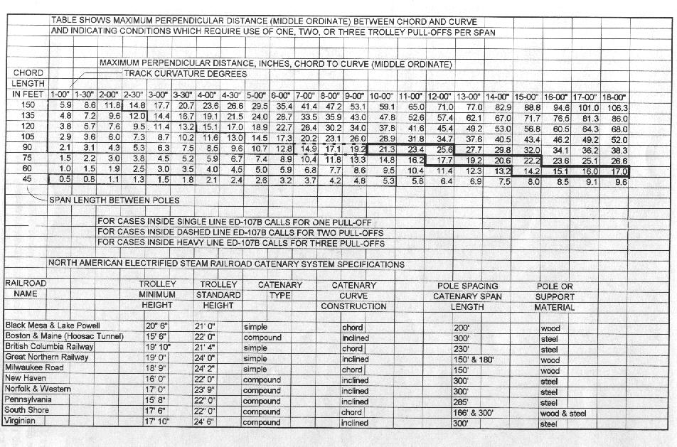
On a model railroad, chord type catenary works very well. The length of each chord, i.e.: the pole spacing must be designed to fit the track curvature, and if this is done there will be no problems with wire alignment. A table is included as a guide on what chord length to use on each curve radius.
Inclined catenary presents a number of problems for the modeler. In order for the trolley wire to form an arc, the messenger must pull it into an arc. As a result, the messenger wire is under tension. Although it can pull the wire to form an arc, it hogs the wire vertically at the same time. The result is a wavy trolley wire. Another problem with inclined catenary
Is that stiff is that stiff pantographs can easily push it up from being inclined to being horizontal. The pan will then hook hangers in the catenary and pull them down. I built some inclined catenary on the Denver HO Club layout, and friend's Great Northern Y-l did just that. The only inclined catenary I have seen which worked well was built by Pennsy modeler Bill Kachel, using 1/32 inch piano wire. This wire is heavy enough to hold its shape without having tension on the trolley wire or the messenger wire.
POLE MATERIALS
For my Milwaukee Road catenary, I use 1/8th inch bronze brazing rod. Such poles are approximately one scale foot in diameter and that is approximately correct, Bronze poles look very good, they are quite strong, and they are cheap. Brazing rod can be purchased from welding supply stores in three foot sections for 40 cents to 60 cents per rod. These rods can be sawed, drilled and soldered as easily as brass. When paint or chemically blackened, they look almost like wood. Real wood poles are a poor choice for a layout. Strong poles have a diameter which is way out of scale. Poles made of 1/8 inch dowel are so fragile they will snap oft if you bump them and they are not strong enough to hold catenary wires under tension.
The Pennsylvania and the Virginian used steel "H" columns. These can be modeled with the brass "H" beams manufactured by the BRAWA Company. They are not quite as strong or as cheap as bronze poles, but they will work and they look good.
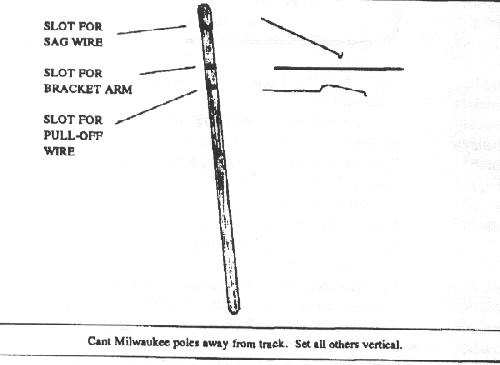
I use I use 1/32 piano wire for the bracket arms which support the catenary. The sag wire which supports the bracket arm is made of .015 piano wire. Guy wires, if needed are also made of .015 wire. For the catenary display I drilled holes in the brazing rod and soldered the bracket arm and sag wire into them. If a large number of poles are to be made, it is quicker and cheaper to use a Dremel saw and cut slots into the poles. The bracket arm and sag wire are then soldered into the slots. The excess solder can be removed with a file. If holes were drilled in a large number of poles, the modeler can expect to wear out a large number of drill bits during the electrification project.
POLE SPACING
In areas where the track is straight the poles supporting model catenary need to be spaced far enough apart to capture the feel of the railroad being modeled. On curves and in yards they need to be close enough together to hold the catenary within two scale feet of track center. For pole spacing on curves, refer to the chart showing catenary span lengths as they relate to degrees of track curvature. On straight track the prototype distances could be used if the train layout is large enough, but shorter spacing can look good. The Milwaukee and Great Northern used 130 foot spacing as their standard on straight track.
I built some catenary which had 126 foot spacing (17.5"). It captured the feel quite well while allowing me to build standardized sections on a jig. The jig holds 36 inch sections of wire and I allow 1/4 inch on each end for lap joints. If 130 foot (20") sections were built, then each 36 inch piece of catenary would have to be laid out differently The pole locations relative to the catenary would be different for each section, since 20 inches does not divide evenly into 36 inches. My Milwaukee catenary test track uses 105 foot (14.5") because that spacing allowed me to use several poles on a display which is short enough to fit into my car. The Virginian Railway display uses 224 foot (31") spacing. This was chosen rather than the real 300 feet because it worked better with my jig and because two 300 foot catenary spans plus their deadends would call for an HO display which would be over seven feet long. I feel that 224 feet looks good and captures the feel of the prototype.
Keith Newsom uses a pole spacing of 105 feet because it works well with his track plan. His catenary is built in place rather than in a jig.
Heavy electric modeler, Jack Culver, builds his catenary in place on his layout. He uses 100 foot spacing over straight track, with the spacing over curves and switches shortened to fit the track layout The 90 foot (12.5") spacing on his catenary display was dictated by a desire to keep the display small.
POLE INSTALLATION
Poles need to be attached firmly to the layout. To accomplish this, some of the wooden framework needs to be under the layout at pole locations. I find the best method for installing brazing rod poles is to push them into 1/8 inch holes. I put a little Elmer's Glue into the hole before installing the pole. That assures that the wood will not shrink away from the pole over time. Since Elmer's does not firmly grasp metal, I can still raise or lower the pole at a later date by hitting it with a hammer. I can remove it by pulling it up with pliers
When the poles are first installed, every effort should be made to install them at the correct height. You should make some catenary, plan how you want to attach it to the bracket arms, and decide how high above the rail you want your trolley wire. Then you should install one pole in such a way that the wire height is correct. Next use a scale rule or a wire height gauge to determine how high the bracket arm is above the rail heed. The other poles can be installed quickly by setting them at that same height.
INSULATORS
Insulators look good, but can be time consuming to make, My Milwaukee insulators are made with #11 Seed Beads, The high voltage insulators are made with Seed Beads and sequins. The insulators made by Jack Culver actually insulate the catenary from the poles. His were carefully made on a lathe using plastic and threaded screw material.
MODEL TROLLEY WIRE HEIGHT
The trolley wire must be constructed at a height which is within the WORKING range of the pantographs in use. That height is roughly two or three scale feet below the height of the pantograph's maximum extension, Higher wire heights can cause electrical contact because the pantograph may be unable to exert pressure against the wire. The NMRA recommended maximum wire height is 22 scale feet. As a result, most model manufacturers utilize pantographs which have a maximum extension of 22 scale feet, Because of the limitation created by the pantographs, modelers should utilize a wire height of 20 scale feet, or they should acquire custom built pantographs. Properly designed pantographs of the types used by the Milwaukee, Great Northern, Pennsylvania, and others will reach 27 feet, They will work fine under a 24 foot high wire.
The reason that the pantograph's maximum extension needs to exceed the wire height is to accommodate upward deflection of the wire. When! built a small layout, I found that pantographs were deflecting the wire upward by a scale foot at mid span, The spans were 126 feet between poles. -
WIRE CENTERING
For good operation, the wire should be kept within one foot of track center. In no case should it be more than two scale feet from track center. Destructive dewirements may result if these standards are exceeded. In order to accurately align your catenary when building it, and in order to maintain the alignment, you will need to make an alignment gauge. Without one it is hard to visually determine whether or not the wires are in proper alignment. When tight radius curves are in use, pantographs mounted at the ends of some locomotives may swing far out from the track center line. if the wire over the curves is offset to accommodate those locomotives, the wire will be unsuitable for any other type of locomotive.
WIRE STAGGERING
Staggering is a method of spreading pantograph shoe wear by stringing the catenary in a zigzag line. Most American railroads chose not to do this because the rocking of the locomotives spread the pantograph wear satisfactorily. The practice of staggering originated in Europe. There, the mainline rights of way were often maintained to perfection, rail joints were parallel rather than staggered, and the catenary was originally strung at dead center above the tracks. When the catenary wore grooves in the pantograph heads, European railroads remedied this by staggering the wires. American tracks were never manicured and the wires were never strung at dead center. Instead, they were hung at somewhat random locations anywhere plus or minus nine inches from track center. The only time a modeler would want to stagger the wires if they are modeling AMTRAK's new Northeast Corridor wire work, the Black Mesa & Lake Powell, or BC Rail's Tumbler Ridge line. The catenary on all of these lines was designed by European consultants and is staggered
if the wire is to be staggered, set it at one foot inside of track center at the even poles and one foot outside of track center at the odd poles. When modeling catenary which is not staggered, just make sure that you do not set all of it at dead center.SWITCHES AND DEADENDS
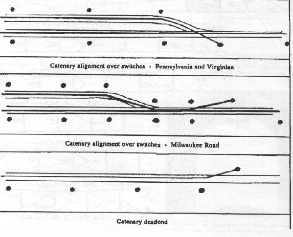
When building catenary for pantographs, there is no need to put a frog in the wires above switches. On many railroads, the catenary for the diverging track simply passes through the catenary for the main track, with the diverging wire lying on top of the main track trolley wire. On the Milwaukee, the two catenaries came together and ran parallel for a short distance, then one was deadended, In both types of wire work over switches, both catenaries are interconnected. The interconnection assures that a pantograph cannot push up on set of wires without pushing up on the other set. This prevents the pantograph from riding 25 feet on a siding for instance, and then hooking its horns into the 24 foot high main track wires as they converge over a switch.
Catenary is deadended to the side of the track rather than at its end. This provides a clear path for the tracks to continue on, or for rolling stock to run off the end of the track without tearing down the catenary.
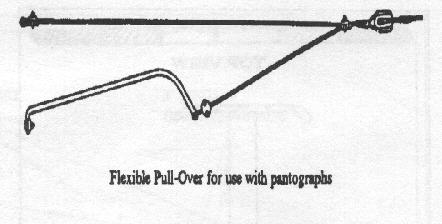
CATENARY PULL-OFFS
At every point where the catenary changes direction, pull-offs are needed in order to hold it in alignment. These pull-offs are typically on curves, through switches, and at deadends. The natural tendency of a wire under tension is to make a straight line between two points. Without pull-offs, the catenary will not line up with any-thing in between. Pull-offs consist of a bracket which is designed to clear pantograph shoes and a cable which anchors the bracket. I have found it to be quick and simple to make one piece pull-offs out of .015 piano wire. An example was shown in Part I, May 1995, page 6. A drawing of a prototype pull-off appears in the drawings which are an attachment to this article.
PAINTING
I find that part of the enjoyment of having catenary is being able to see it. Catenary which is black or dark brown is hard to see. I paint mine copper oxide green to give it visibility. The Milwaukee's catenary near Seattle was that color. As a result, it was easy to see it from a quarter mile away. Most of AMTRAK's ex-Pennsy and New Haven catenary is green also.
If the catenary is to be painted, I recommend Floquil brand lacquer based Railroad Colors. With these, it is easy to mix any color you want, and it adheres well to metal. My copper oxide green is a pale mixture of Jade Green, Refer White, and Grimy Black. After painting the catenary, clean the bottom of the trolley wire with Methyl Ethyl Ketone. The MEK will dissolve and remove the paint quickly. Just put a small amount on some cloth and run it along the underside of the wire. Use a small mirror to inspect the wire for any remaining paint.
|
|
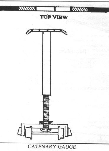
Dummy pantograph shoe has notches sawed in at center, one foot, and two feet The zone from one foot to two feet is painted yellow. The zone from two feet to the end of the pantograph horns is painted red. The pan head can be raised up and down on a bolt mounted in an old passenger car truck, or a block of wood which is grooved to sit on the rails. Because this gauge is adjustable vertically as well as horizontally, it can be used to check wire height as well as lateral alignment. |
WIRE LUBRICATION
Most railroads found that by lubricating the pantographs and trolley wire, they could keep wire and pantograph shoe wear down to a negligible level. The Milwaukee Road applied a mixture of graphite and axle grease to the locomotive pantographs. I found lubricating models to be valuable also, especially if steel trolley wire is used. Steel is quite hard and can be somewhat abrasive to the pantograph shoes. In order to prevent wear, I applied a small amount of sewing machine oil to the trolley wire. I ran a Q-Tip dipped in oil along the bottom of the wire.
FUNCTIONAL OVERHEAD POWER SUPPLY
On prototype railroads, the wires are negative and both rails are positive. A model railroad will run quite well if wired that same way. The pantograph always makes good contact because it tends to scrape all dirt and oxides off of the trolley wire. The wheels tend to make excellent contact with the rails since all of them are grounded instead of only half of them. The drawback to this system is that steam engines and diesels can no longer run on the same railroad.
Electrics will run just fine from two rail supply, but it seems like a waste to build a functional overhead wire system and not use it if the pantographs are going to touch the wires, then the wires must be properly aligned. Dead wires must be just as carefully constructed and aligned as live ones. Otherwise, the catenary will be hooked by the pantograph's of moving locomotives.
Two types of compromise systems offer an alternative. The first alternative involves having the electrics run from a power supply which is connected to the overhead and one rail. The steam engines and diesels operate from a separate power supply which is connected to both rails. With the electrics, all wheels on one side are grounded while all those on the other side are insulated. The electrics must always remain headed in the same direction to operate in this system. if they are put on the track backwards, no current will flow through them. As a result they must be banned from wyes and return loops. The second compromise possibility uses only one power supply for electric and non-electric motive power. Under this System, the electrics cannot be separately controlled, and if they are on the track backwards, they will create a dead short. Electricity will pass from the pantograph directly to the wrong rail, without passing through the motor.
Considering the difficulties which are involved in supplying power from the overhead, you might wonder why anyone would want to utilize it for power supply. After all, it is practical to run everything from two rail supply and leave the wires dead. My answer to that is that a lot of satisfaction comes from knowing that the overhead really works and from watching an occasional arc flash as the trains roll by. - Noel Holley